2011-10-03

The Tracked Roadable Amphibian (TRA) project


This dates back to my early teen years as you can see by the faded pages torn from an exercise book. 

I wanted to make something better than a conventional tracked vehicle – one that would really go anywhere and not destroy roads if used on them. 

The basic idea was to design a single huge track that would have vertical axis hinges as well as the usual horizontal hinges of tracks. This would then be fitted to a frame with rollers, guide wheels etc. that would “bend” to enable cornering. 

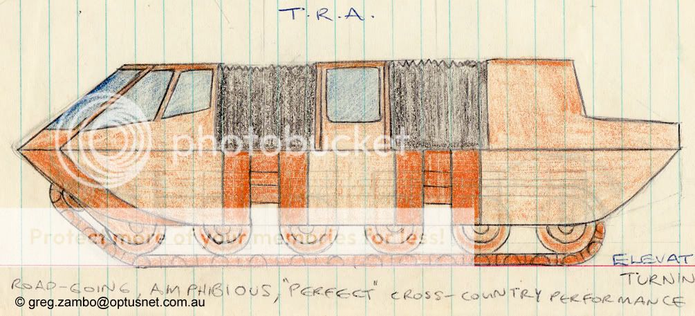
 [Side view of TRA mk.1]
The main advantage of the design is that it would go over anything: mud, water, sand, anything: the whole bottom surface of it is tractive so the weight distribution will be lower than anything else by a major factor. This machine would cruise over sand dunes you can't walk on. Deep snow likewise.
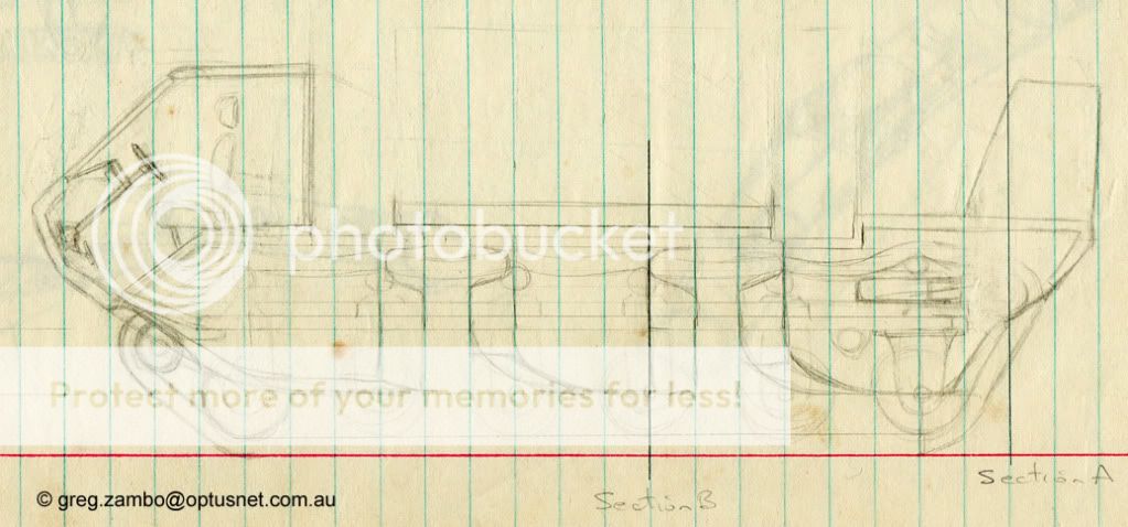
 [Side section of TRA]

[Plan view showing cargo area and cabin]
[Plan view of vehicle cornering]
 [Cross-section showing track wheels and drive system]

There are problems with this idea: first, that track is going to be heavy. Even shaving weight with modern composites it will still be a significant mass in motion and that means more horsepower needed to move it: win some, lose some.

The next matter to consider is turning circle: I have tried to make it as tight as possible but there is a real limit to how narrow you can go. Ingenious overlapping plates on the ends of the track links would allow some tightening. You also need to provide a graduated turning system for perfect cornering: a corner should start at the front of the machine and progress to the rear (if you get the idea).

Suspension could be provided with the use of springing on the main wheels and some might also be provide by making the track links themselves springy - but too much in either area could result in failure of the track system.
Keeping the track on it's rollers and wheels could be a major issue since the track flexes in more than one plane: adding the shape changes of running over uneven ground and the need for a spring tensioner at one end of the track loop you are looking at some pretty fancy issues there - I still think it could be done though.

The TRA Mk.2
The Mk.1 design looked okay but the track seemed to take up a lot of space in the machine and I liked the idea of being able to lower the total weight and area used by using a sneaky design modification – so the Mk.2 was born.

My approach was to consider the track as a zigzag that could e either stretched out or compacted. In the stretched state the track feet attached to zigzag links by long arms would all fold into a narrow channel while also decreasing the overall weight of the track loop since the stretched section needs less links to go the same distance. On the front end a driven track pulley would pull the stretched links from the back and compact them into the wide layout for use underneath the vehicle. On the bottom of the vehicle, runners for the track would ensure that it stayed open.
The drawings show the basic idea but the design was never finished properly: unlike the simpler design, I was not happy with the second hinge axis problem created by this type of track. 
 [Mk.2 track shown extended]

  [Mk.2 track system in cross section with wheels and rollers]

Now, I could mess with the part shapes in my 3D modelling software to improve or disprove the idea. Still there it is folks, anyone wants it, go ahead, just mention me somewhere okay?

2011-06-25

Raupenschlepper Ost

This is my new project, Called RSO for short. Just like the Willys Jeep project, it will be as accurate as I can make it - hey, I might even put both into a scene.


The big issue for me is always getting enough photos and plan detail to make a good replica.
Typically the plans available online are so coarse that they are useless. Photos, on the other hand are magic if you can get enough of them and of the right things, you can trace directly over them for near- perfect detail.  The track is messed up but this is only a WIP.

2010-11-01

Tintin Rocket

This little model took 64 minutes including making the image texture. I did it since someone on a BBS was asking how to make it, and I realised the only way to really tell them was to try it myself. I'm pleased it came out so well. I have not been doing much with Blender lately and it is good to keep my talents in practice.

2010-08-30

Some Solid Works


Helmet
I made this from flat sheets of cardboard and it took a bit of work to get the parts to meet up nicely. The visor opens on hinges and although it might not look like it you can see very well from inside. There's plenty of room inside for all sorts of extra stuff too. Having worked out the method of making compound objects from sheet cardboard I could do it much faster now. In some places e.g. the bottom ring it's four or five layers thick so it's pretty strong -
I've even dropped it once or twice and it hasn't dented.

  
Mark VII Blaster
This was patched together out of junk I had lying around at the time including an old game controller for the handgrip.
It has a purple light and a noise circuit that run off batteries in the handle. the switch on the  side changes the noises it makes. The small speaker inside adds a bit of realistic weight to it so it feels about right to hold.
The blue section is a removable charge cartridge that plugs in - presumably there would be different cartridges for  various  types of "blast".
This kind of thing is a real challenge to get right - to get it looking like it was made that way.
It seems to have collected dust and grime that really add to the realism.


2010-04-15

Aircar 3: the TX project

As you will see on the link,(click the heading!)  DARPA is asking for submissions for a 4 seat offroad capable VTOL vehicle for the Marines. This links in some new technology such as computer navigation and hybrid power with specs something like that flying car people have been asking about ever since we learned how to fly. Since I have already made an Aircar or two, I thought I'd have a go at predicting what this thing will look like when it arrives (planned for 2015).
Here are my first sketches. I made ducted fans since this looks to be the way to go from the specs, and they are as big as will fit the size limits, so that's one key limitation right there.


Side elevation - here you can see the first design problem clearly: for strength, the pair of lift fans and their mounting bridge are one piece which pivots on a vertical axis to fold them on land - but as seen here there is a bit of an overhang past the wheels which may get them caught in trees or other obstacles in offroad mode - I tried moving the wheels further apart but then you need six wheels and that pushes the weight up.


Front elevation above.


Ortho view above.
Critical issues for the design definitely include the weight of the ducted fans at the top of the vehicle - this could make it hard to get good offroad performance, but then the offroad vs. VTOL performance is really the crunch with this project: how will they deal with water crossings, steep hills and mud while still keeping the flying parts operational? A ductfan covered in mud will not work well, and too much mud on the wheels and underpan could push up the weight so that VTOL is a lot harder, even if you have clean fans.
I can't wait to see what the big aircraft companies come up with.

2010-04-10

Aircar 2: The Cutlass


This is the Cutlass. It's kind of a sketch at the moment, but the basic ideas have been with me for many years.  The main element of the design is that the props suck air from the top of the plane to increase lift as much as possible for short takeoff.  As an Aircar it also has the advantage of  a large cabin area. The propellers are variable pitch and they can be feathered for improved gliding.


Here is the back end with most of the flaps and the props. Ideally the engine would be electric but I am not sure battery technology has got good enough for one of these.


The underside. The rear wheels are covered but the front ones can be retracted completely.
Hieght adjusters on all the wheels may be needed to get liftoff, but that is easy to do since you need roadworthy suspension anyway.


Here it is parked with outer wings folded. This is only a sketch, which is why the window edge looks odd.